Fingers have an important role in the function and aesthetics. Finger amputation may result from congenital cause, trauma, infection and tumours. The loss of a finger leads to functional and psychological problems. The finger amputation may be rehabilitated with dental implant-retained finger prosthesis. The biomechanical behavior of implant-retained finger prosthesis systems including the reliability and the stability of the implant–abutment and implant bone interface plays an important role in its functional longevity inside the bone [1].
The structure of dental implant is directly connected with a bone that would cause the non-uniform stress pattern of bone and might induce biomechanical overloading failures in implant and bone [2].The success of implant-retained finger prosthesis is determined by the implant loading, consequently, which leads to the bone loss around the implant. The characteristic of the force is a determining factor in implant loading. This overloading would cause the micro-damage accumulation at bone and results in bone loss around the neck of the implant [3]. Furthermore, it is reported that the initiated loss of bone mostly around implant neck evolves deeper into the bone [4,5]. Finite element analyses (FEA) of stressand strain fields have indicated that stress concentration occurring exclusively in the cortical bone near the necks of implants is responsible for the initiation of overload-induced bone resorption in this region. This analysis technique has thus, been applied to optimize implant design, with an attempt to improve the biomechanical environment in jaw bone/implant systems and reduce bone resorption due to occlusive overload [6–8].
Our main objective was to evaluate stress distribution in the finger bone when the loading force is applied along the long axis of the osseointegrated implant using finite element analysis.
Material and Methods
1. CAD and Finite elements modeling:
CAD modeling
The finger bone model containing cortical bone and cancellous bone was constructed by guiding from radiographs of the metacarpel bone model. Then, the model was discredited into the geometric (i.e. CAD) model shown in [Table/Fig-1] into smaller and simpler elements containing cortical bone and cancellous bone was constructed. A metacarpal block 3696 mm-length, 1462 mm-width and 1379 mm-height was modeled. The Titanium implant model based on bone level implant (Astratech Osssospeed implant systemTM, Mölndal, Sweden) of 4.5 mm diameter and 14 mm length was selected from one case that was with implant retained finger prosthesis in Golden Jubilee Medical Center, Mahidol University, Thailand. The prosthesis system was composed primarily of 3 parts: (a) the implant, (b) the abutment and (c) the abutment screw [Table/Fig-1].
The 3D CAD finger bone model containing cortical bone and cancellous bone along with prosthesis system was made

The models were designed in Solid Works 3D software (Solid Works Corporation, Massachusetts, USA) and transported to ANSYS 13 (ANSYS Inc., Southpointe, Canonsburg, PA, USA).
Finite Element modeling
Finite element model (FEM): FEM was created by discrediting the geometric model into smaller and simpler elements [Table/Fig-2].
3D finite element model of the finger bone containing cortical bone and cancellous bone and the prosthesis system
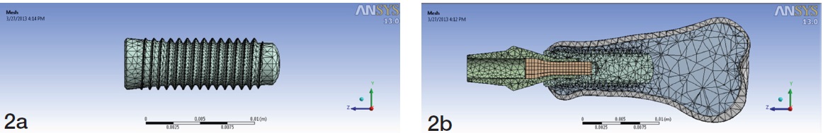
The FEM model consists of total 75713 four-node tetrahedron elements; 3058 elements of cortical bone, 17688 elements of spongy bone, 3169 elements for abutment, 483 elements for screw and implant.Tetrahedron elements in cortical bone, spongy bone, abutment screw and implant corresponding to elements in ANSYS element library with each node having three degrees of freedom.
Material properties:
The material properties adopted were specified in terms of Young’s modulus, Poisson’s ratio and density for the implant and all associated components [Table/Fig-3] [9]. All materials were assumed to exhibit nonlinear and thermal strain effects.The elastic properties, loads and constraints used in the model were taken from published data.
Mechanical Properties of materials used in this study
| Mechanical Properties of materials used in this study |
|---|
| Material | Young’s modulus (MPa) | Poisson ration (v) | Yield strength (MPa) |
|---|
| Ti-6 Al-4V | 110 | 0.32 | 800 |
| Cortical bone | 14.5 | 0.323 | 180 |
| Spongy bone | 1.37 | 0.3 | 35 |
Loading Conditions
Loading of the implant was done in 3-D with forces of 50 N from top for 1 second, along the long axis of the implant simulated pushing action. The end fixed support consisted of the carpal end.The solid model resulting from the intersectionof implant and jaw bone represents the assumption of complete osseointegration, restricting any relative displacement between implant and bone.The FEM model was fixed at the carpal end.
The interface between implant and bone was modeled as a continuous bond. This implies an ideal osseointegration, without any relative motion at the interface. In other words, the implant was rigidly anchored in the bone, showing a fixed and same type of bond at all prosthesis material interfaces.
Results
When the force of 50 N loading was done on top of the implant along the axis, the stress distribution ranged from 0.006 to 31.673 MPa.
The maximum von-Mises stress was located at the head of abutment screw and the minimum von-Mises stress is located in the apical third of the implant fixture [Table/Fig-4]. The maximum stress within abutment screw was 3.59% of the yield stress.
Stress distribution in the implant and the finger bone

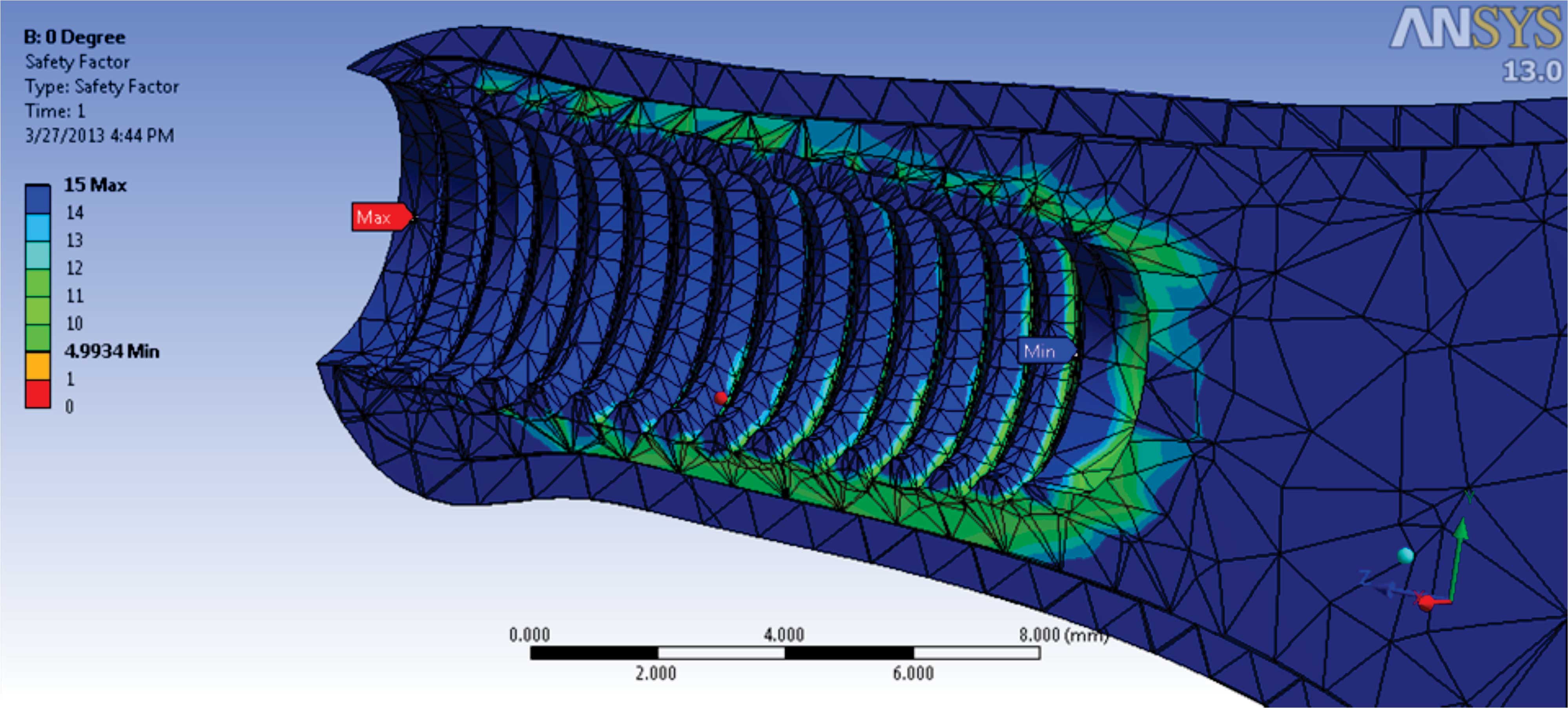
The weakest point was calculated by safety factor which was located in the spongy bone at an apical third of the fixtures [Table/Fig-5]. The strongest point was at the collar of the fixture. It also showed that 4.9 times yield stress of spongy bone was needed for the deformation of the spongy bone.
Safety factor in the implant and the finger bone
Discussion
FEA has become an increasingly useful tool for the calculation of the effects of stress on the implant and surrounding bone. A key factor for the success or failure of a dental implant is the manner in which stress is transferred to the surrounding bone. FEA allows investigators to predict the stress distribution in the contact area of implants with cortical bone and around the apex of implants in spongy bone.
It has long been recognized that both implant and bone are stressed within a certain range for physiologic homeostasis. Overload can lead to bone resorption or fatigue failure of the implant, whereas, under loading of the bone may cause disuse atrophy and subsequent bone loss. In most FEA models, the bone–implant interface was assumed to be perfect, simulating 100% osseointegration [9]. The generation of high stress distribution or concentration in the bone should be avoided to achieve stable osteointegration for implant restoration. Therefore, overload in a biomechanical system causes stress on implant or mechanical components leading to bone loss around the implant and/or mechanical failure. Peri-implant marginal bone loss was considered as a sign of possible overload. Therefore, estimation of peri-implant horizontal and vertical bone loss is an important parameter for evaluation and prognosis of implant success [10]. Many authors have considered two-stage surgery for the implant placement primarily for two reasons; to prevent early failure due to loading and to prevent infection [11,12]. The number of stages for implant placement depends on the primary stability of the implant and the quality of the bone. In 2013, Amornvit et al. presented one-stage technique for the implant placement in implant retained finger prosthesis [13]. This technique is safe, reliable, more efficient with less operating time and hospital visits compared to the two-stage technique and more predictable procedure in metacarpal and phalangeal bone.
In this study, an implant inserted into a metacarpal bone for finger prosthesis, has been analyzed using a virtual model. This model is designed in to examine in vitro the effect of the combined dynamic load acting along the long-axis on this prosthesis. When the force of 50 N loading was done on top of the implant along the axis, the stress distribution ranges from 0.006 to 31.673 MPa. The finger prosthesis presented here indicates the existence of a higher stress concentration at the head of the abutment screw, i.e., the implant withstood the maximum amount of stress compared to any other component of the model.Maximum stress within abutment screw was 3.59% of the yield stress. The strongest point was at the collar of the fixture. The minimum stress was located in the apical third of the implant fixture.The result also indicated that 4.9 times yield stress of the spongy bone needs to be applied for the deformation of the spongy bone. In addition, the cortical bone is stiffer than the cancellous bone. According to the results of the present study, it was found that in under loading, more stress is transferred to the cortical bone than spongy bone which is less dense and has more strain.
Many clinical studies have reported significant bone loss around the implant neck of failing implants, and various hypotheses have been proposed to explain this bone reaction [14]. Animal experiments [15] and clinical studies [16] have shown that bone loss around implants that may lead to implant failure was associated in many cases with unfavourable loading conditions. Inappropriate loading causes excessive stress in the bone around the implant and may result in bone resorption. Therefore, it is valuable to investigate the stress/strains in bone and their relation to different parameters of implant and bone. The optimization of the contact area between the bone and the implant can be an important factor in increasing the durability of the prosthesis [9].
The CAD model used in this study implied several assumptions regarding the simulated structures. The structures in the model were all assumed to be homogeneous, isotropic and to possess linear elasticity. The properties of the materials modeled in this study, particularly the living tissues, however, were different. Also, it is important to point out that the stress distribution patterns may have been different depending on the materials and properties assigned to each layer of the model and the model used in the experiments. Thus, the inherent limitations in this study should be considered.
Conclusion
Finite element study showed that when the force was applied along the long axis of the implant, the maximum stress was located around the neck of the implant and cortex bone received more stress than cancellous bone. So, to achieve long-term success, the designers of implant systems must confront biomaterial and biomechanical problems, including in vivo forces on implants, load transmission to the interface and interfacial tissue response.